LIN
LIN is a cost-effective and deterministic communication protocol designed for connecting Electronic Control Units (ECUs) with smart sensors, actuators, and controls. EcuBus-Pro's LIN module provides comprehensive features for developing, analyzing, and testing LIN networks in compliance with LIN 2.x specifications.
Adding Device
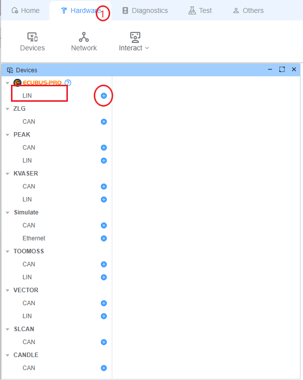
Through the top menu bar, select Hardware, then click the + button on the right side of devices that support LIN to add a device.
Supported Hardware:
| Manufacturer | Protocols | Abilities |
|---|---|---|
EcuBus LinCable | LIN | Supports error injection, can perform conformance testing, and supports PWM output |
| PEAK | LIN | |
| KVASER | LIN | |
| Toomoss | LIN | Support 12v voltage output/input, 5v voltage output |
| VECTOR | LIN |
Configure Device
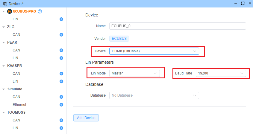
After clicking add device, you will be required to input device settings:
- Custom device name
- Device channel
- Working mode, Master or Slave
- Baud rate
- Bound database (optional)
IMPORTANT
Some features described below may require importing a LIN Description File (LDF). For more information about LDF, see the database documentation.
Schedule Table Management
IMPORTANT
Available when LIN is working as a Master node. The corresponding device needs to load the corresponding database.
Schedule table management allows periodic execution of a specific schedule table from the LDF database.
Add LIN Interaction
- Open the Network interface
- Click the
+button under theInteractiontab in theLinnetwork on the left side of Network to add an interaction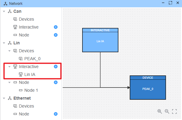
Open LIN Interaction
- Open interaction configuration
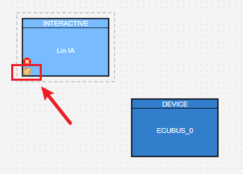
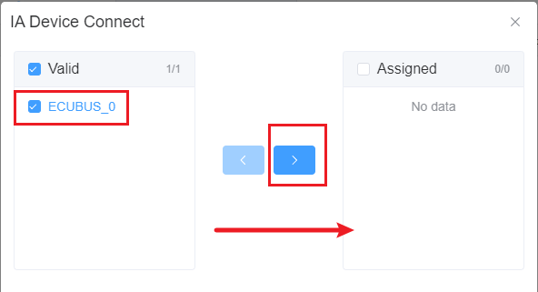
- Configure the LIN device connected to the interaction
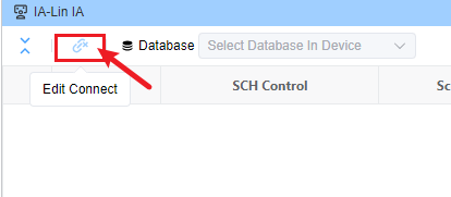
- Select the LIN device you want to connect
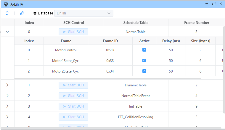
- View and manage existing schedule tables. You can temporarily skip a frame in a schedule table by turning off Active.
Node Simulation & Signal Editing
IMPORTANT
The corresponding device needs to load the corresponding database.
Configure and simulate LIN nodes to test network behavior and dynamically update signal values for corresponding nodes.
Node Configuration Steps
Add Node
- Open the Network interface
- Click the
+button under theNodetab on the left side of Network to add a node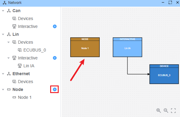
Configure Node
- Open Node configuration
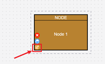
- Set up Node connected device
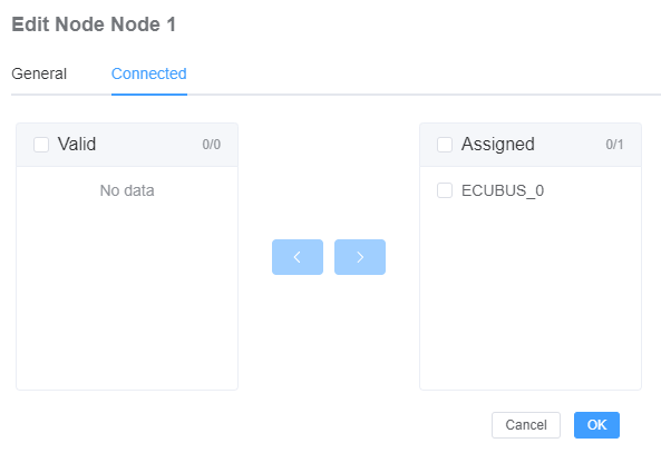
- Select the network node that the Node simulates (Need to select the corresponding LIN device, and the corresponding device has a bound database)
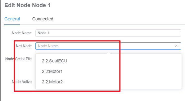
- Open Node configuration
Signal Value Editor
- After the Node is configured, you can edit the signal values of the configured Node
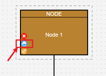
- Modify signal values (Only signals published by the configured Node can be modified. For example, in the figure below, only the signal values of
Motor2as a publisher can be modified)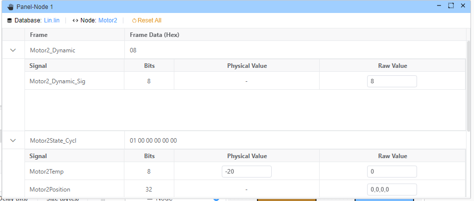
- After the Node is configured, you can edit the signal values of the configured Node
Node Simulation After the Node is configured with a network node, it will automatically simulate the Node sending signals. For example, when the device Lin works in Master mode and Node1 is configured as a
Motor2Slave network node, when a request forMotor2is received, Node1 will automatically respond to this frame and give a Response.