CAN Example
This example demonstrates basic CAN communication setup and usage in EcuBus-Pro.
Network Structure
The example consists of three nodes:
- Node 1 (Brown) - Signal generator node
- Can IA (SkyBlue) - Interactive analysis interface
- SIMULATE_0 (Blue) - CAN bus simulator
The nodes are connected in a CAN network topology, with Node 1 sending signals through SIMULATE_0 device, which can be monitored and analyzed in Can IA.
Features Demonstrated
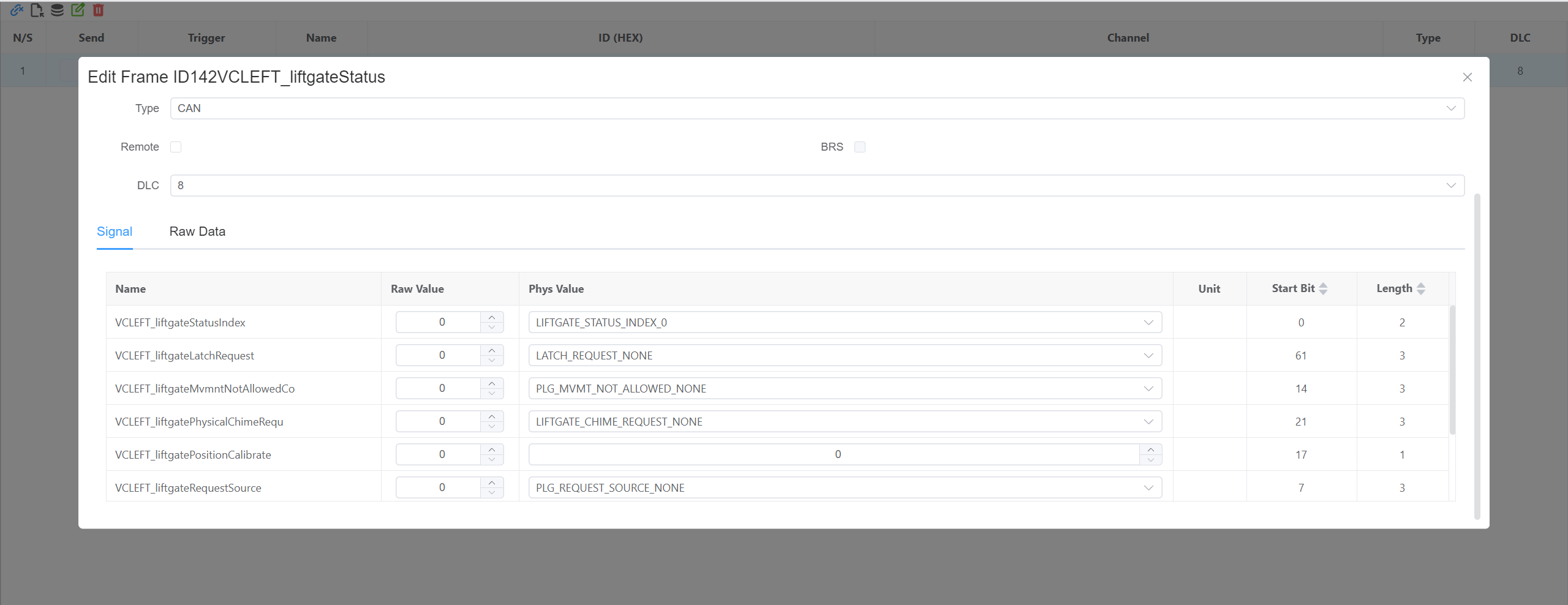
Message Transmission
- Node 1 runs a script that periodically updates signal value
- Signal: VCLEFT_liftgateLatchRequest (cycles through values 0-4)
- Update interval: 1000ms
typescript// Node 1 script import { setSignal } from 'ECB' let val = 0 setInterval(() => { setSignal('Model3CAN.VCLEFT_liftgateLatchRequest', val++ % 5) }, 1000)Data Visualization
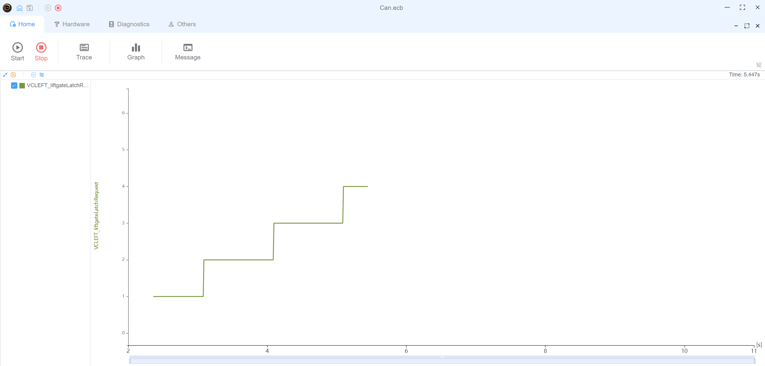
- Real-time signal graphing in Can IA
- Message trace logging
- Network topology view
Interactive Controls
- Start/Stop frame sending
- Signal value inspection
Graph
- graph signal
VCLEFT_liftgateLatchRequest
- graph signal
Usage
- Load the example configuration file (
Can.ecb) - The network topology will be displayed in the Network view
- Start the simulation to see Node 1 generating signal values
- Use Can IA interface to:
- Monitor signal changes
- View message trace
- Watch real-time signal graph
- Inspect message details
This example demonstrates how to set up automated signal generation and monitoring in EcuBus-Pro, making it ideal for learning basic CAN communication concepts and signal analysis features.